Six Years Ago…
I began to build a bass bow! but other things intervened, and I had to set it aside for a bit. I posted about it back then on my other website:
Bass Bow Beginning
But then I got another little block of time, and I made more progress. That was fine, but it was still not terribly high-priority, so it was again set aside while I did what life demanded. (I had gall-bladder surgery somewhere around that time…kinda captures the attention somehow… I had posted about that progress, and the surgery, as well. But it really set me back as far as productivity goes. Sigh…)
Bass Bow Progress
Annnd, as luck would have it, the gall-bladder surgery disturbed the existing scars from bowel surgery four years earlier, so I ended up with three hernias along the old scar, (sigh…) and was back in the hospital again for hernia repair. (Getting reaalllly tired of this game!)
But now… Everything seems to be healed up and I am once again productive, at one thing or another. 🙂
Completing a Bass Bow
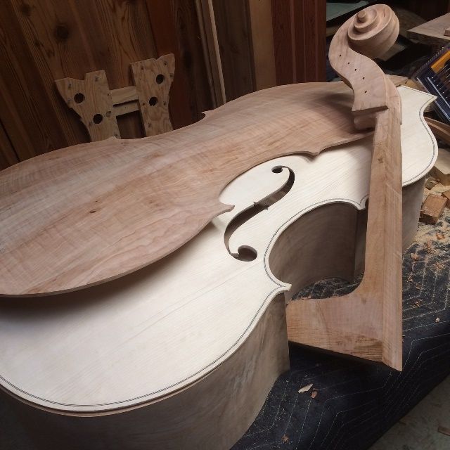
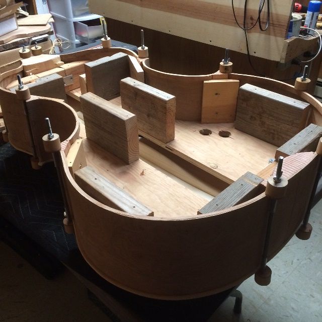
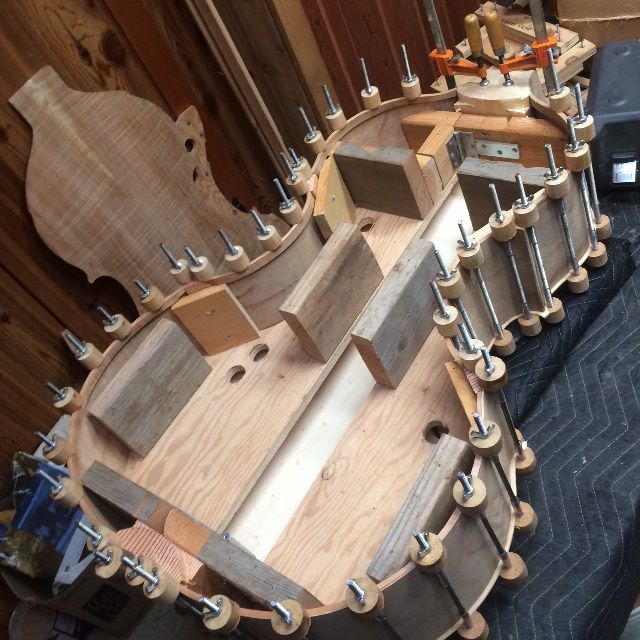
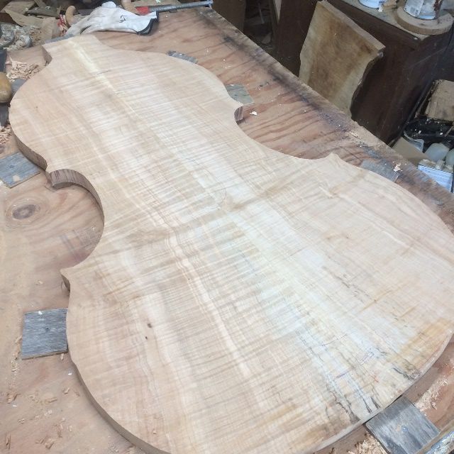
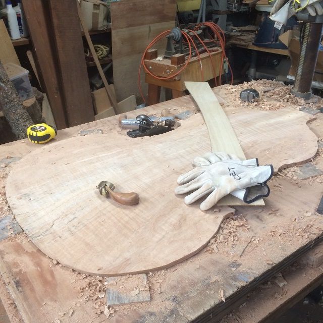
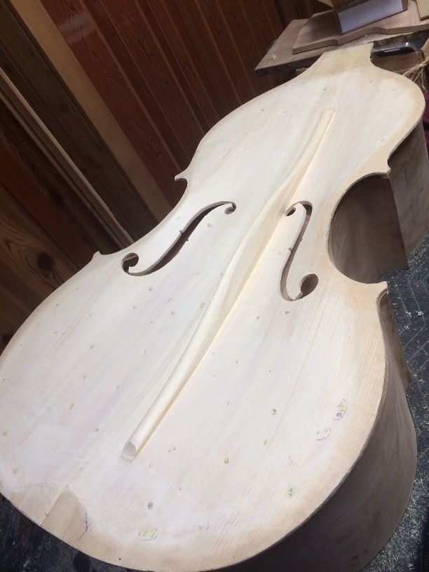
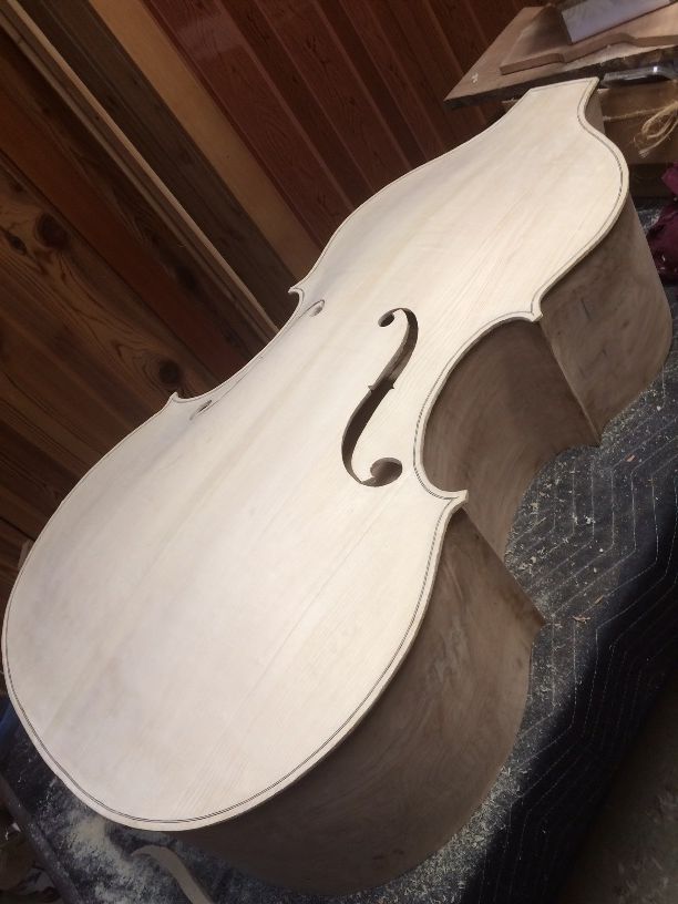
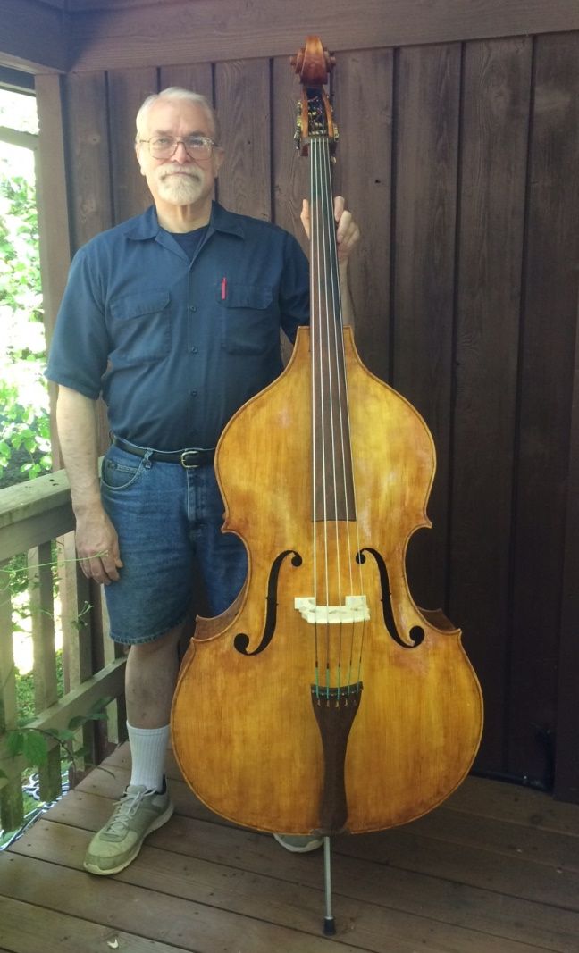
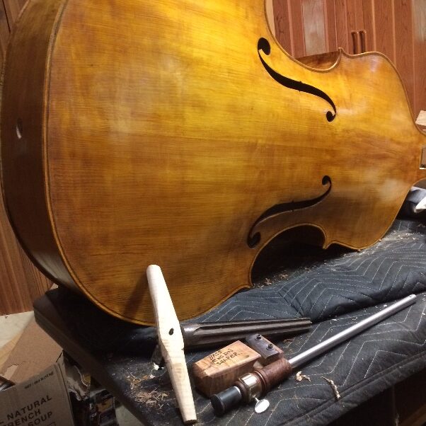
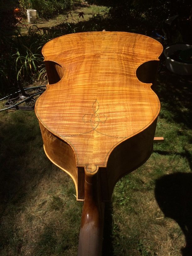
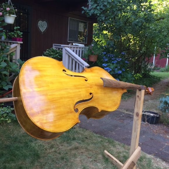
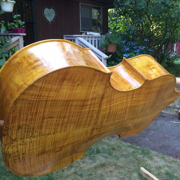
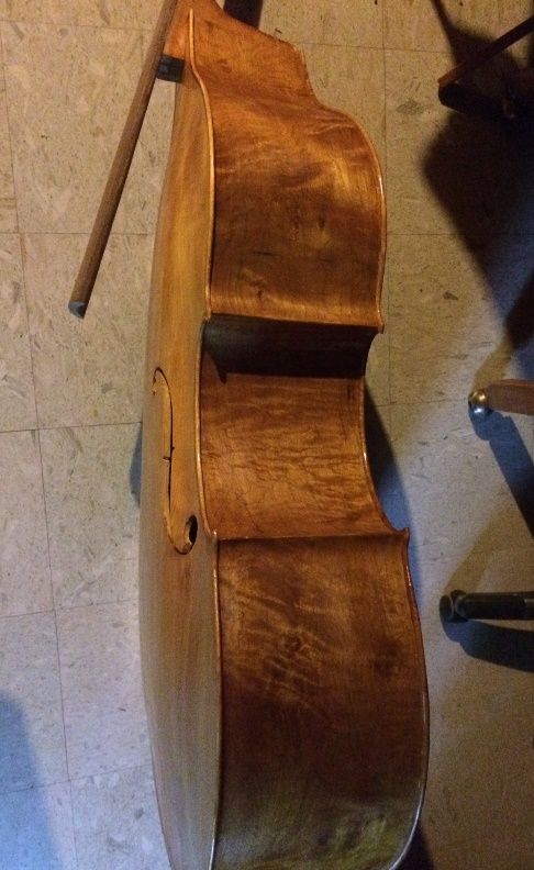
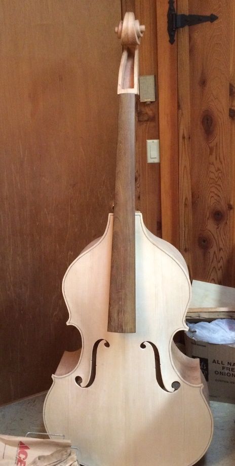
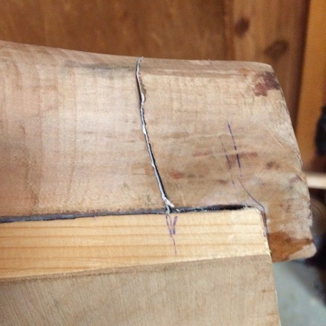
I built my second upright bass, a five-string, 5/8-size double bass with a removable neck for safe transport, and I was struggling to adjust the sound. The bow I had was annoyingly cheap, and soft, and the hair as fine as I would expect on a violin bow… so it was frustrating, and I kept thinking, “I need a better bass bow!” So, the time had come!
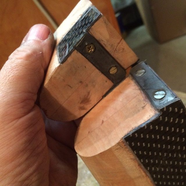
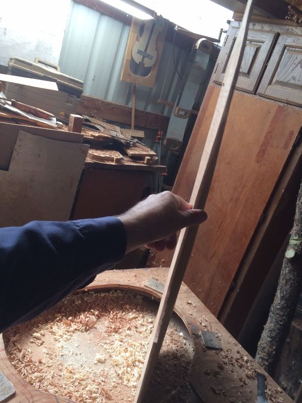
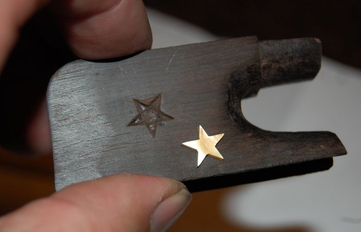
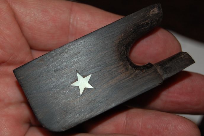
I knew where the Hickory bow was, which I had begun years before, and most of the things I had bought to go with it, so I got moving on it. I finished inlaying the second gold star on the side of the frog, cut gold Mother-of-pearl for the slide and the dot on the end of the adjuster screw, and started on a ferrule.
Beginner’s Errors!
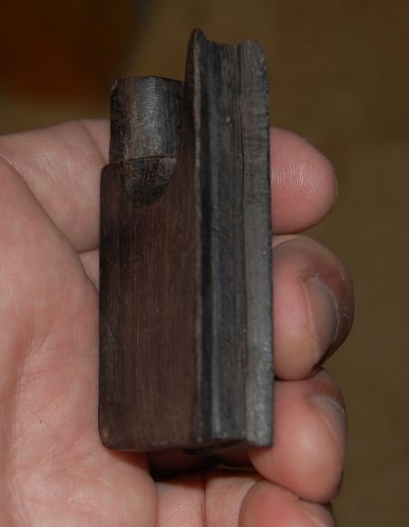
All you bowmakers are already shaking your heads, because you know (as I did not know, that I should have built the ferrule first, and then made the frog to fit the ferrule, instead of the other way around. It is much simpler to carve hardwood to match an existing metal structure, than to bend and braze (that’s what silver-solder is, technically) metal together in an attempt to match an existing wooden shape. (Ah, well, never let it be said that I passed up an opportunity to learn things the hard way…)
Anyway…the ferrule was a real pain to make, because I failed to do it first. The under-slide, by comparison, was a piece of cake.
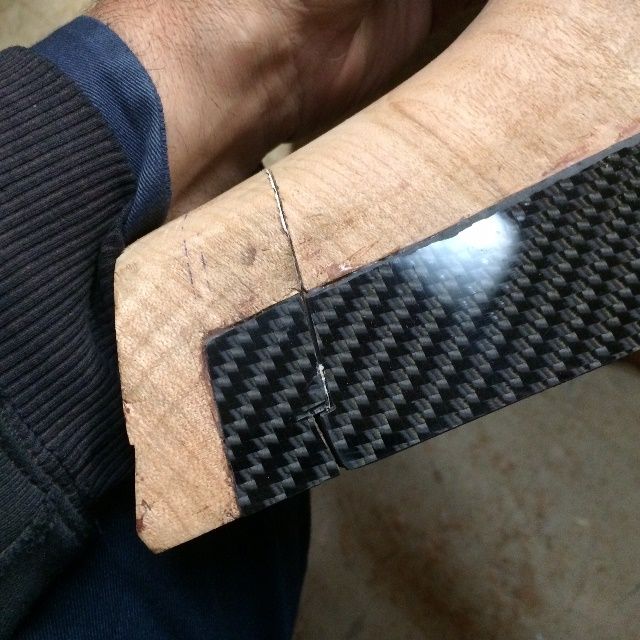
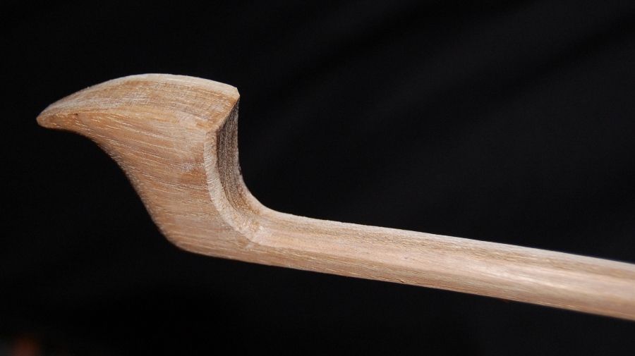
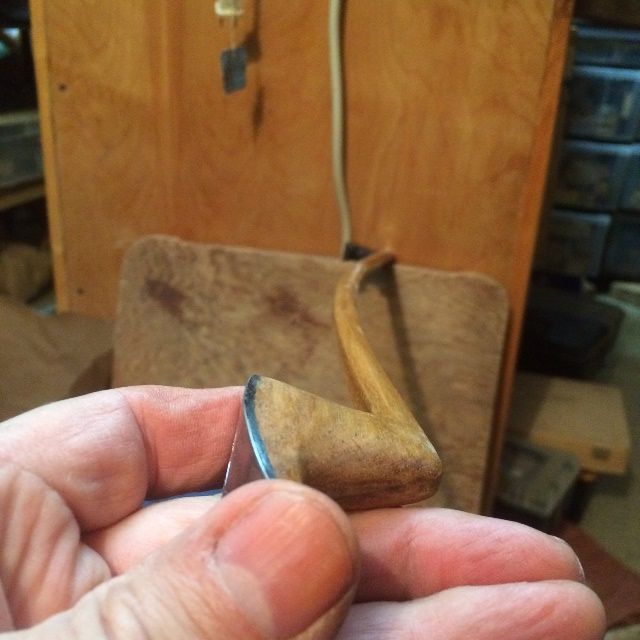
I had to make a new metal bow-tip, as I had accidentally made the original one a tiny bit too small. Also, I had chosen to use stainless steel, because it was cheap, easily available, and very durable. (Another beginner’s error: Yes, all of the above is true, but it is also much harder to cut, solder, file, and drill holes in than silver would have been.)
At any rate, I got back on the project, and in a day or so, had what looked like a promising bow! But I couldn’t find the hair I had bought. (I remember seeing it, and I remember putting it somewhere so I’d be sure to find it again. Must have been a really special place…I have no idea where it went.)
I looked and looked for the hair I had bought, but had no luck: I finally decided to quit messing around, and just order more hair. Usually, there are specialist suppliers I would patronize, and I prefer to do so, but they all would take a week to ten days to deliver: so I ordered through Amazon, and had it the next evening! (Amazing!)
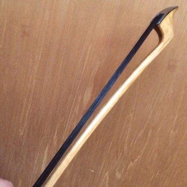
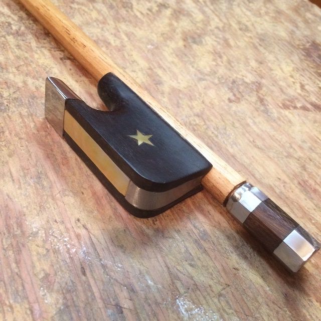
While I was waiting, I added the leather thumb-pad and the wire windings.
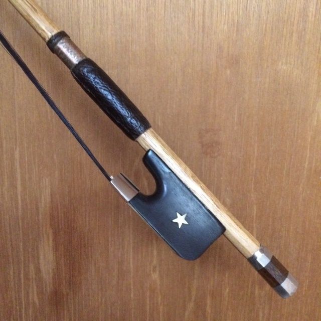
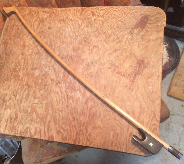
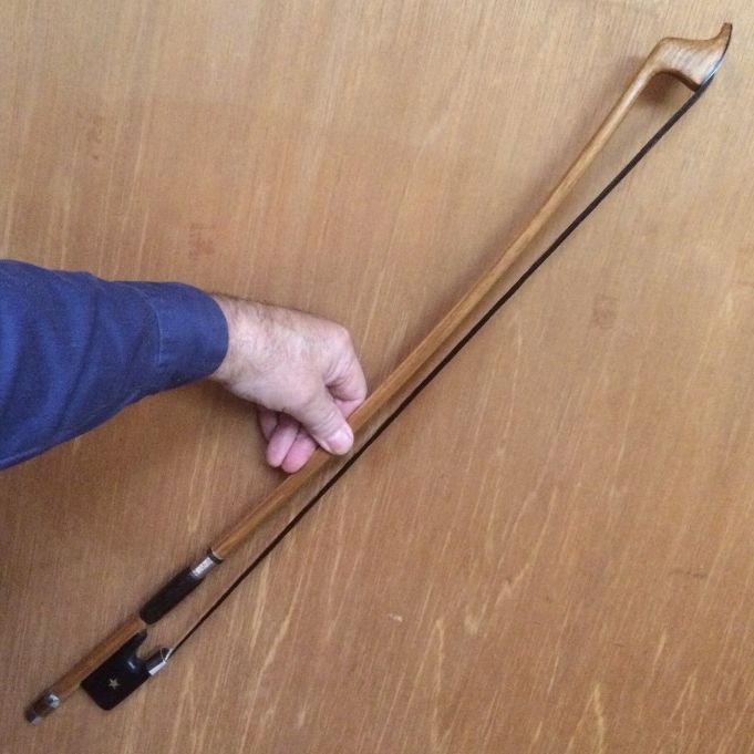
And…that is what the new bow looks like!
And it Works!
I am grateful to be able to say, it works well! I get better tone and more volume with this bow than I did with the cheap student bow I already had.
Undoubtedly, a bow made of Hickory cannot be expected to match a good bow made of Ipé wood, let alone one made of Pernambuco. But this bow is quite satisfactory, and I feel pretty good about the project as a whole. I may try making another bow of Ipé, or Bois d’Arc, though, before I attempt a bow of Pernambuco.
Thanks for looking!


.JPG)
.JPG)
.jpg)