Gotta have a stand for the bass…can’t let it just lie around the house.
Heavy base-plate adds stability for the five-string double bass.
Nearly 4″ thick particle-board base-plate lowers the center of mass.
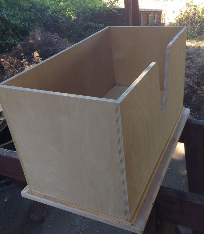
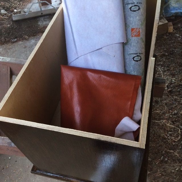
Exterior of 1/2″ birch plywood for strength and beauty. Ready for varnish
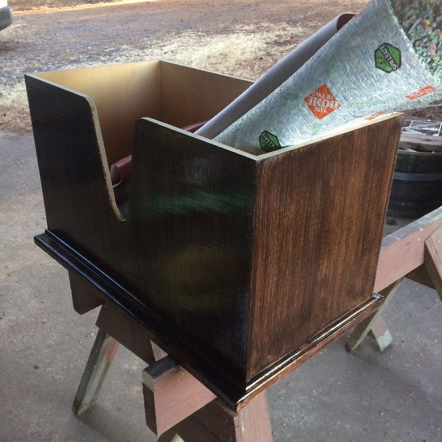
Varnish complete: ready for upholstery.
Carpet padding with vinyl upholstery.
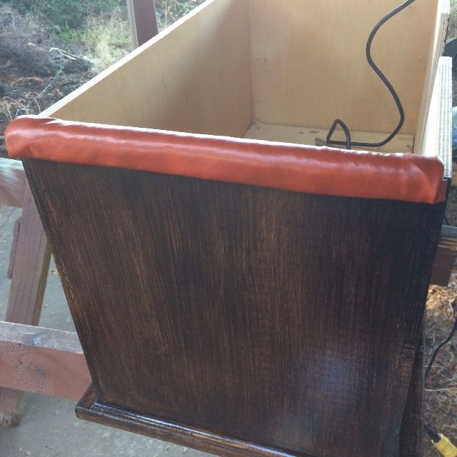
Upholstery begun…outside view.
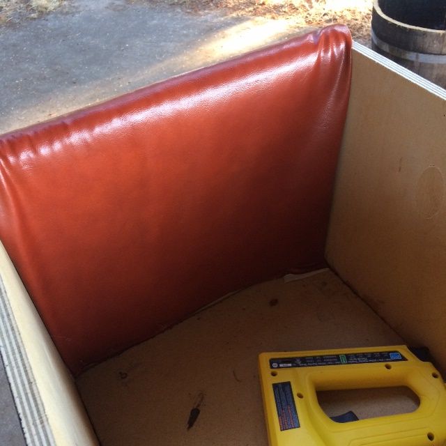
Inside view.
Upholstery completed.
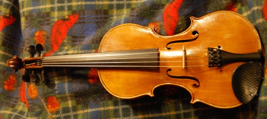
Bass stand with the bass, secure against tipping.
Looking good! Safe, too!
Travel Case Coming!
The next project has got to be a travel case for this bass. A “Travel-bass” with a removable neck is less than optimal without a case in which to travel. And such cases don’t seem to be readily available for reasonable prices.
So, it is back to the drawing-board for me. 🙂
Probably looking at a foam-core fiberglass case. Shouldn’t be too much harder than building a boat. 🙂
One of the problems with creating a double bass whose neck is removable for traveling is that there has to be a way to connect and disconnect the neck. Thus you have a choice– will the fasteners be visible from the outside, or hidden inside?
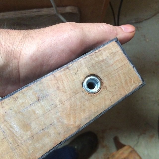
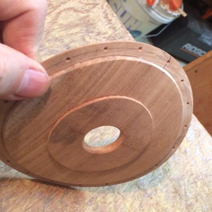
I have seen several examples of both, and I really prefer the hidden fasteners approach. BUT! That also mandates that there be a way to access the interior to tighten or loosen the fasteners. I have chosen a 3/8″ diameter bolt (tensile strength exceeding 5,000 pounds) and a large flat washer embedded in Epoxy on the inside of the neck block. The bolt extends through the washer and the neck-block and engages the threaded insert in the maple wood of the neck heel (see below.) So…the next step is to consider a side-access port through one of the C-bout ribs,
Threaded Insert in the heel of the removable neck.
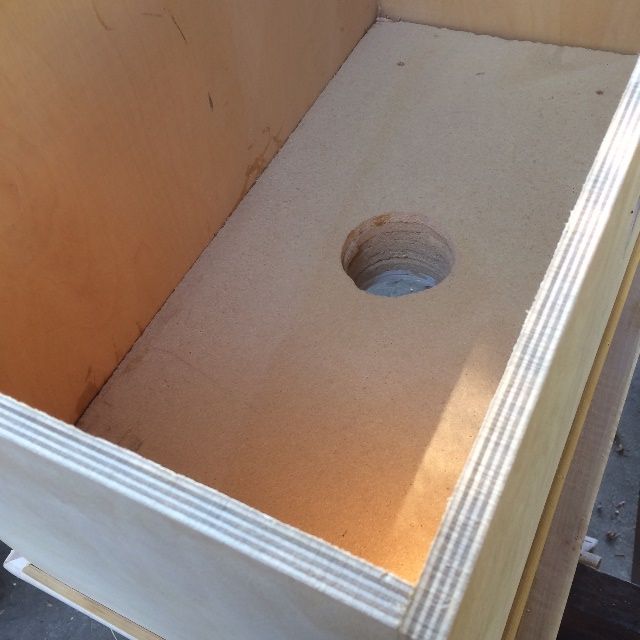
Access port
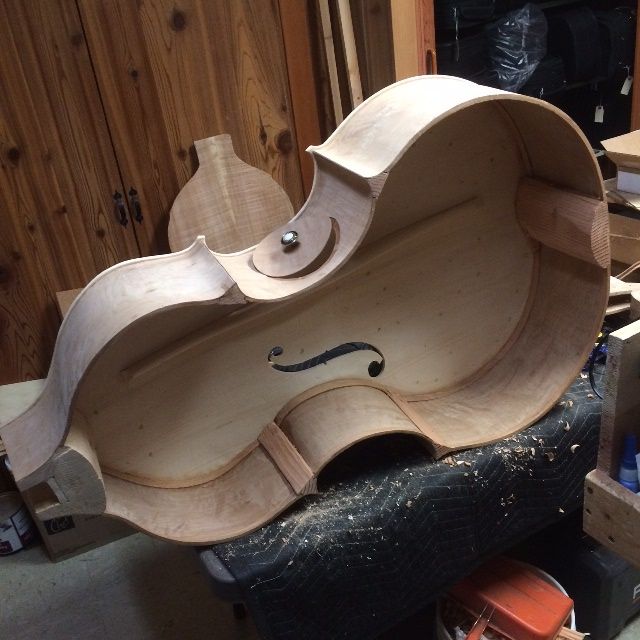
I chose to make the access port through the bass-side c-bout rib: the player will reach up through the port with his or her right arm to access the single bolt in the neck-block. As an added bonus, the soundpost is also easily accessible, as it will surely need to be re-positioned after having the bass apart for travel. (In fact, it is so nearly guaranteed to be loose, that I intend to provide a pocket in the instrument case for the soundpost, as well as the bridge, the tailpiece, and the neck assembly, etc. That way there is no question: as you reassemble the neck, you will also re-set the soundpost, after the strings are on, but before it is up to tension.) Finally, as another luthier pointed out, if there is ever repair-work to be carried out inside the bass, this access port makes it a much simpler task, thus saving money and time.
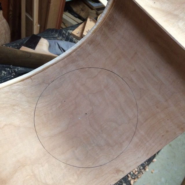
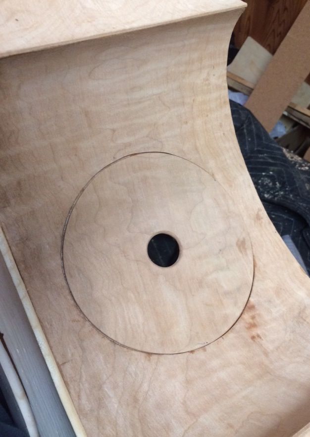
So: how to carry out the access port plan? I positioned the proposed hole on the bass-side c-bout rib, roughly centered, and laid out a 5-3/4″ circle. I cut out the circle using an X-acto knife, then smoothed the cut edges with a file and sandpaper. I wanted to use that piece for the closure, as well, so I couldn’t afford any damage to either the rib or the cover plate.
Side access hole laid out.
Initially, I had thought I would employ a drawer-pull-type handle as a means to open and close the access port, but I didn’t care for the looks, so, after further reflection, I chose to make a simple “finger-hole,” instead. I reinforced the single-thickness of rib-stock with two more, especially near the center, so that the rib would be stronger, and so that the edge of the rib where the finger contacts it will be 6mm thick instead of 2 mm, thus much more comfortable.
Proposed access cover plate with pull-knob.
Side-access cover plate with finger hole.
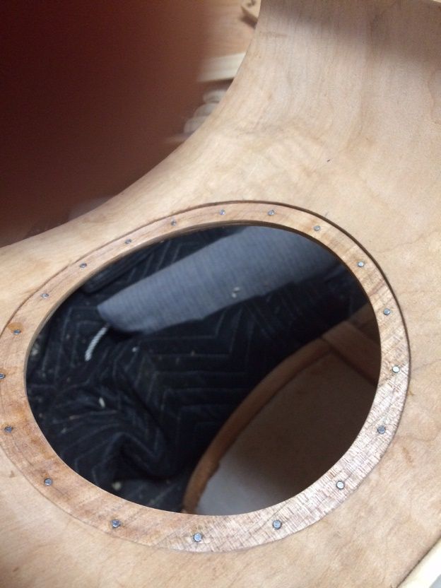
I reinforced the actual c-bout rib by adding a second thickness of ribstock to the entireinside of the existing rib, and I cut a slightly smaller hole in it so that the closure plate had a shelf to rest against. Also, this is the surface into which the neodymium magnets will be inset, to hold the closure plate in place.
Side access hole with reinforcement plate inside and neodymium magnets.
(I realize that the above photo looks a little as if there were a plexiglass cover on the hole, but those are not reflections: you are looking through the hole at some pads behind the bass body. I was using the pads to protect the front plate, earlier.)
I added the reinforcement to the cover plate and sanded the interior of the finger-hole to be very smooth.
Reinforced cover for side access port, with holes for neodymium magnets.
Cleaning up the interior
While the glue was drying on all the above assemblies, I took the time to complete the shaping of the blocks and linings, so as to be ready to close the corpus, once all the interior work is done.
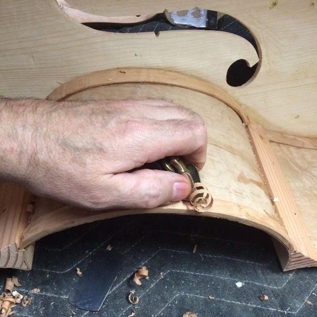
Planing the ribs to shape.
I used a knife a gouge and a small plane to shape the linings and blocks. Then I used a scraper to ensure that it all was acceptably smooth.
Shaping the blocks.
Neck Set
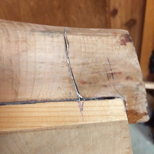
I had checked and re-checked the fit of the neck-heel into the mortise in the neck-block, until all the measurements were correct, and then I had drilled a pilot hole through the neck-block into the neck heel. That established the position and range of both holes, so that when I drill for the insert and r-drill for the bolt, the holes will still be in line with one another. I bedded the large plate washer in epoxy on the inside of the Sitka spruce neck-block, so that the bolt would not be able to gradually wear a hole deeper into the soft spruce.
With the neck temporarily in place, I could check to see how much of the excess neck-heel “root” would have to be sawn off and planed flat. You can see, also, that I had glued the heel-block “root” onto the neck-heel proper, using a sheet of paper between them as a “breakaway” layer, so that when everything was correct, I could easily pop the neck free from the root.
Temporary neck-set.Close-up photo of the paper breakaway joint.
As it turned out, hot hide glue does not bond well to carbon-fiber plate. So, after I discovered that the neck-root was actually not glued home, I was forced to choose epoxy as a final bond for the portion of the neck that is intended to remain permanently in the neck mortise. I don’t like doing this, as epoxy is not reversible, but there was no viable option. After making that choice, though, I took a sharpie pen, and wrote, inside the mortise, a notice to any later repairers, that those three joints (bottom and both sides) at the neck root are epoxy. (Sorry)
But I can put the neck on and take it off and put it on again, and it fits correctly, and all the measurements have remained correct.
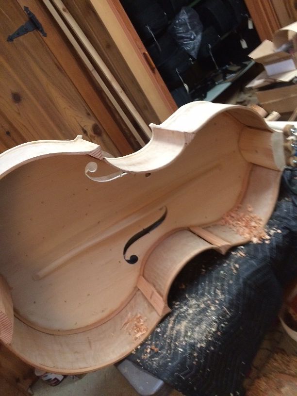
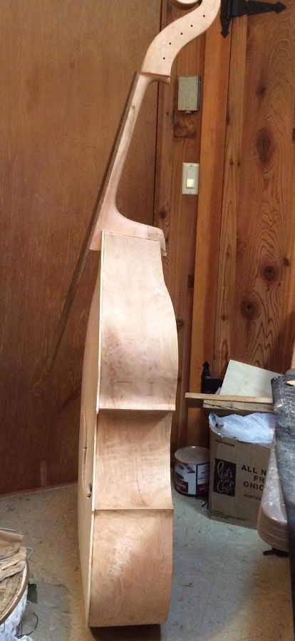
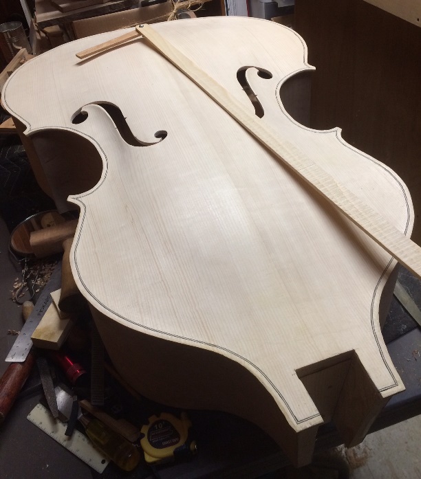
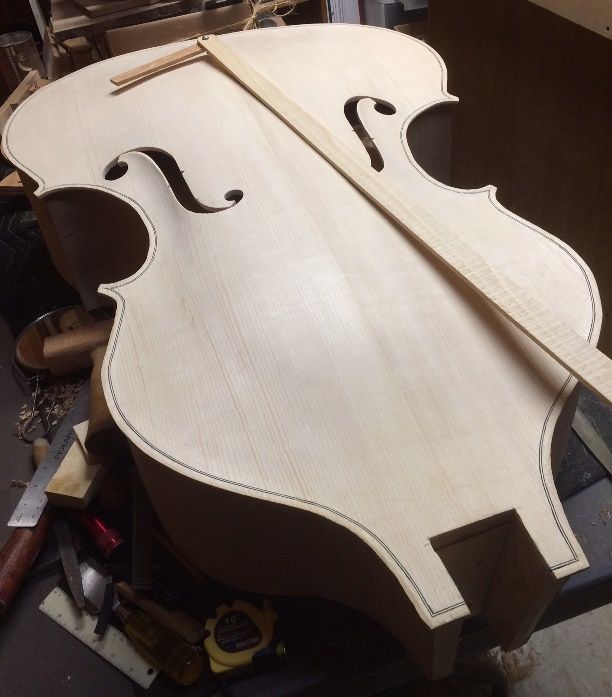
And it is looking pretty good:
Neck set complete.
Next time we will talk about the final work before closing.
There are five measurements to consider in setting a neck on any violin-family instrument:
Obviously, the distance between the nut and the upper edge of the front plate is a critical measurement. One has to know what is required for the instrument in question and make a mark on each side of the neck heel, as to how deeply it is to be inserted into the neck block.
The height of the overstand (distance between the top edge of the front plate and the joint between the fingerboard and the neck.) This measurement is taken from the front of the upper edge of the front plate, right beside the neck, vertically, to the top edge of the neck, proper (joint with the fingerboard.)
The last three are all angles: The plane of the “floor of the neck mortise” must be perpendicular to the centerline of the instrument, and the plane of the bottom end of the neck, proper, must be perpendicular to the centerline of the neck, laterally. If these are both correct, then the fingerboard should project directly along the centerline of the front plate. Any lateral variance from centered is not good.
The centerline of the neck mortise, from front to back, must be perpendicular to the plane of the plates, laterally, so that it literally “connects” the centerline of the back plate to the centerline of the front plate. Simultaneously, the “footprint” of the neck heel should be bilaterally symmetrical about the centerline of the neck heel. The result should be that the plane of the neck face (when viewed from the scroll) should be parallel with the plane of the plates. (No “twist,” or “roll” in either direction.)
Finally, the “Projection angle” should be such that the height of the “projected fingerboard angle” should be at the appropriate height for the instrument in question at the bridge line. (This can either be literally measured as a projection height at the bridge line, or, if you know how high the end of the fingerboard will be if all other factors are correct, you can simply measure it there. The danger in this is that if the other measurements are not quite right, and you simply measure the height of the end of the fingerboard, then the projection angle will be wrong, and you will not discover it until it is too late to correct it. (Ask me how I know!)
Planning the Neck-Set
In the case of a bass, with a removable neck, as well as all the other enormities of a double bass (as opposed to the smaller instruments) I had to not only consider the five measurements listed above, but consider how to achieve those angles reliably when removing and reinstalling the neck repeatedly. It all has to come together correctly without the customer having to “measure” anything, except to correctly carry out the assembly and minimal set-up.
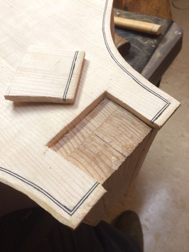
Cutting the Neck-mortise
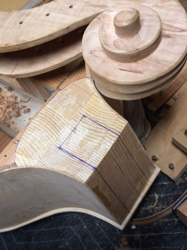
I had already cut the “footprint” of the neck-heel, so I took measurements and laid out the proper shape on the end of the neck-block, where the mortise was to be cut. I worked from the centerline of the neck block, so there was less chance of ending up with a skewed neck.
Neck-Mortise laid out.
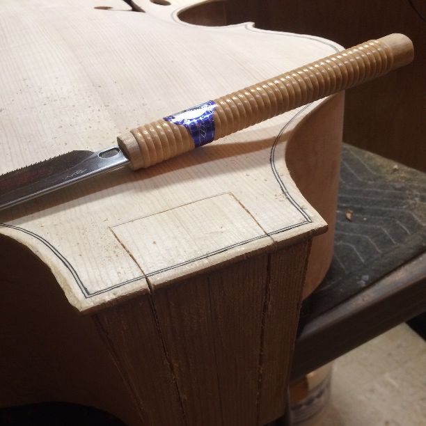
Then I turned the corpus over and began sawing the sides of the mortise, using a thin-bladed Japanese pull-saw:
Sawing the neck-mortise.
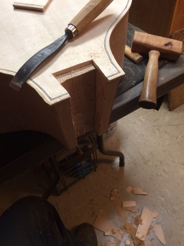
Once I had the two sides sawed out, I sawed across the line between the two sides and separated the rectangle of the front plate wood from the neck block, to expose the neck block, allowing me to use chisels for most of the remaining removal of wood from the neck-mortise.
Ready to chisel out the neck-mortise.
Chiseling out the neck-mortise.
Neck-mortise complete, with homemade projection gauge.
I checked the fit continually until all five measurements were correct, then removed the neck from the mortise, and began fabricating the “removable neck” apparatus that will enable the player to pack up his or her bass and transport it safely.
One of the things that concerned me was the possibility of wood changing shape through wear or stress. And, since the neck is to be secured by a bolt, how can I be sure that the bolt will not gradually wear into the wood, causing a loose fit?
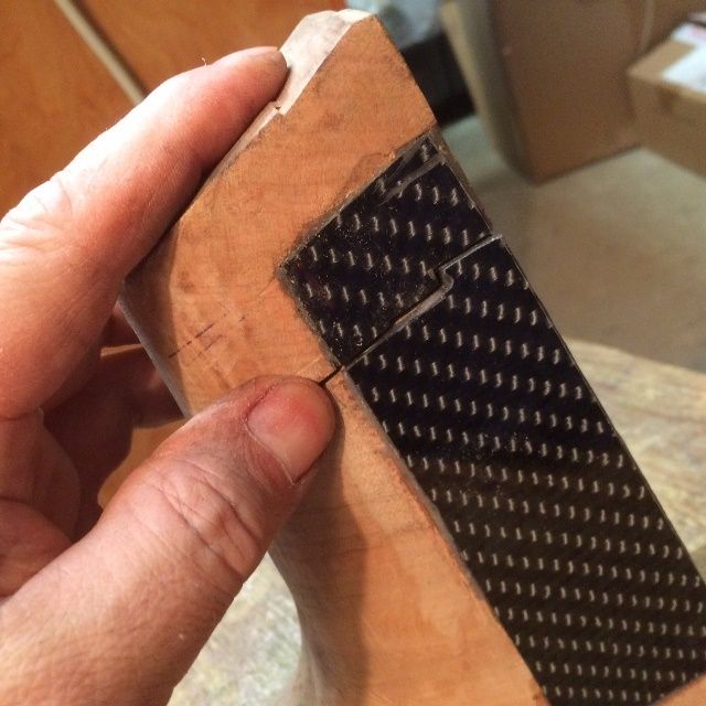
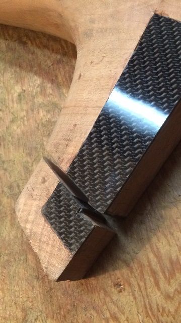
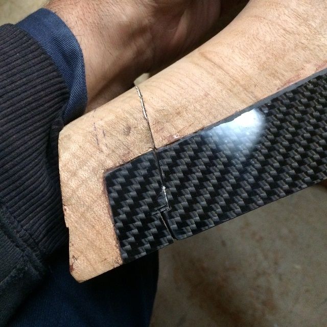
After fitting the neck to the corpus, as outlined above, I inlaid 1/16″ Carbon Fiber plate on both sides of the neck heel, to provide smooth, stable fit every time and simultaneously guard against a heel crack, as the CF plate is not only inlaid into the sides of the neck, but it is bedded in epoxy, so it is a permanent part of the neck heel, providing support as well as a smooth surface to the sides.
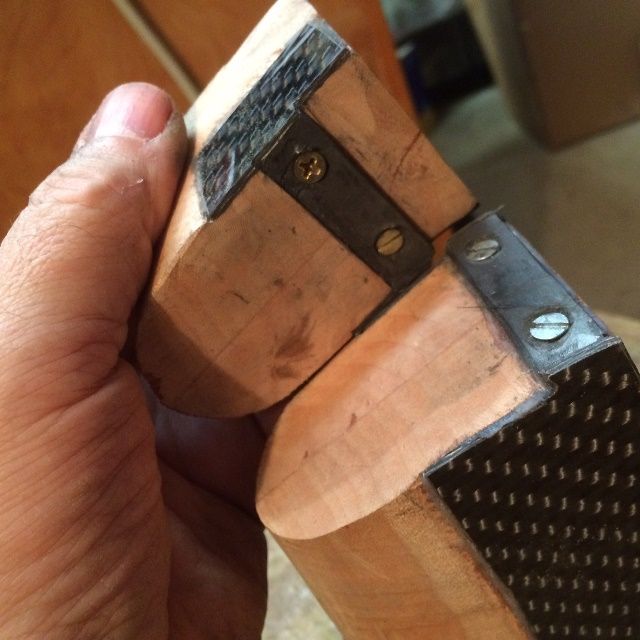
I used screws and epoxy to mount bars of CF across the ends of the “joint” between the neck heel and the portion of the neck heel that will be permanently mounted to the corpus (and secured to the block and button,) so that a bar of CF on the neck heel slides under a similar bar in the mortise, thus providing an anchor of sorts.
Carbon fiber reinforcements and locking joint.
Locking mechanism for five-string double bass removable neck.
Locking anchor-bars for removable neck.
Then I re-attached the two portions of the neck heel using a piece of paper glued between them, so that I could check the neck-set one last time, before gluing the root end in place and drilling the removable portion to receive the bolt. The paper provides a “breakaway joint” that will be relatively easy to separate after the heel root is glued home. it is only glued with a few “stripes of glue on each face, so the paper will tear apart and allow me to extract the removable portion the neck and finally complete the drilling, installation of a threaded insert, etc., and thus complete the neck set.